A robust 3.5-year industry track record in engineering complete electro-mechanical systems for automotive and automation applications.
Maruti Suzuki
2 Years 4 months
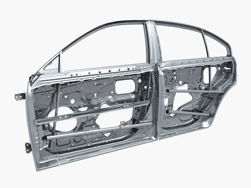
At India’s largest passenger vehicle OEM, I worked as a Door Systems Design Engineer, part of the Body Engineering Division with end-to-end responsibility for the front side door system of a new SUV program.
My role combined design engineering, regulatory compliance, manufacturability checks, and supplier coordination to deliver a door system that was robust, safe, and production-ready.
Emflux Motors

1 Years 2 months


As a Mechanical Design Engineer, I was responsible for designing and programming automated production machinery at this EV motorcycle start-up, where I developed complete mechatronic systems from concept to production, managing assemblies in SOLIDWORKS with over 1,300 components.
Possibillion

3 months
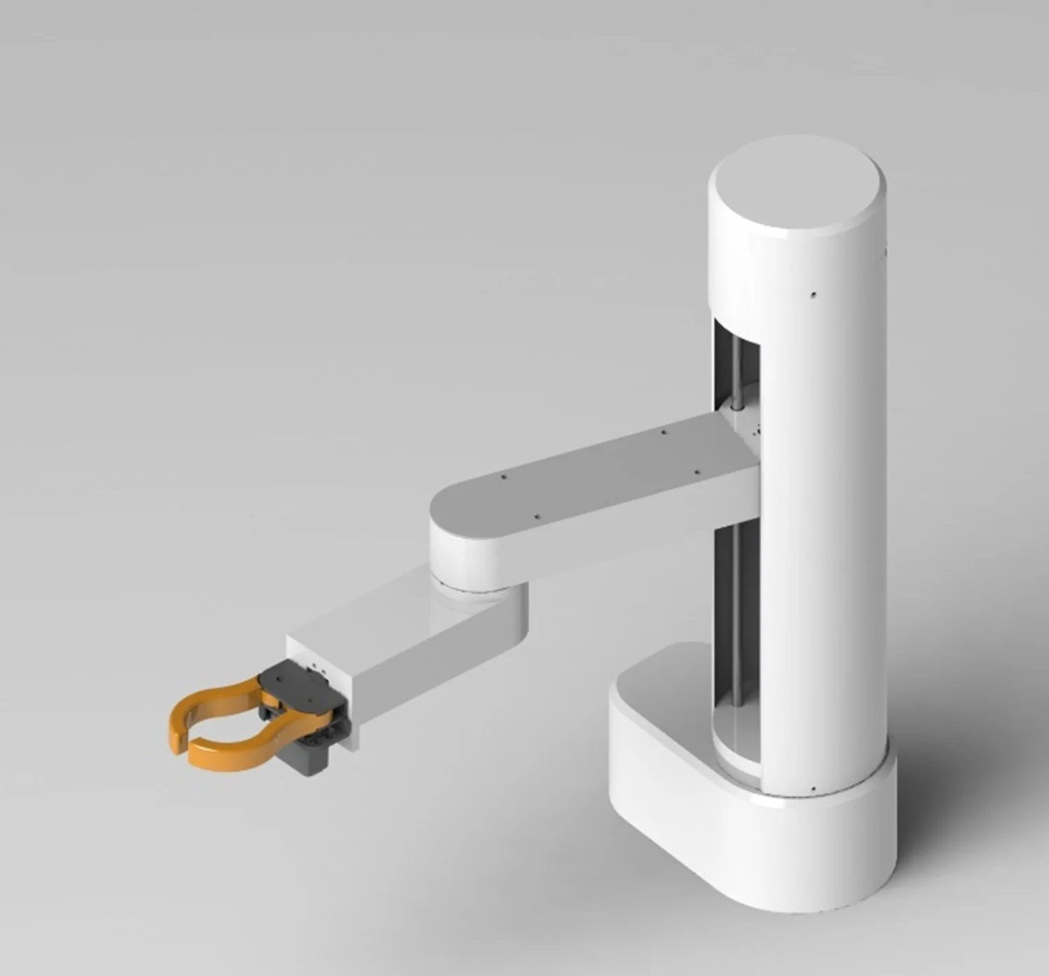
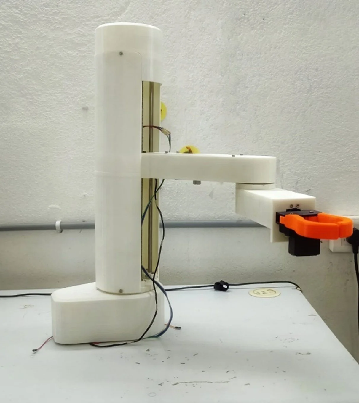
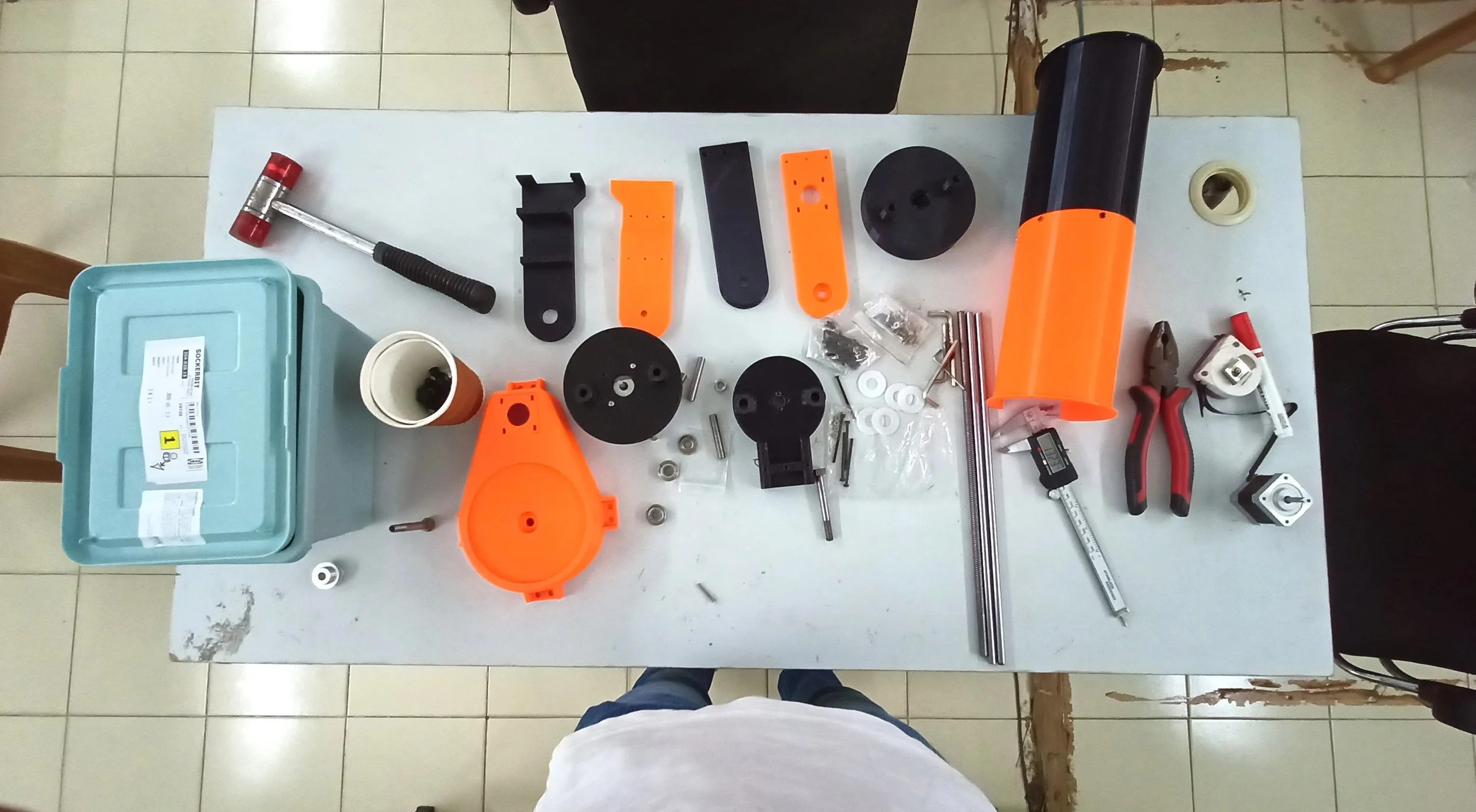
As a Mechanical Design Intern: Designed a 5-axis SCARA Robot for a robotic kitchen. Designed in SOLIDWORKS, selected stepper motors based on required torque calculations. Built a reliable working model by prototyping parts using FDM 3D printer.
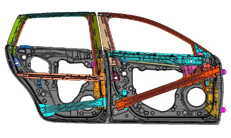
Door Systems Design Engineer - OEM Perspective

System-Level Responsibilities
I started with Class-A surfaces provided by the styling team and carried out detailed section studies to freeze door cutlines.
This required balancing aesthetics, ergonomic reach envelopes, and feasibility for press tooling and hemming operations.
The design was coordinated across press shop, weld shop, paint shop, and assembly shop to ensure seamless manufacturability.
Structural & Safety Engineering
Designed the door inner panel to integrate mechanisms, sealing surfaces, hemming flanges, and trim attachment features. Considerations included DFA/DFM principles, crash load paths, and stiffness optimization.
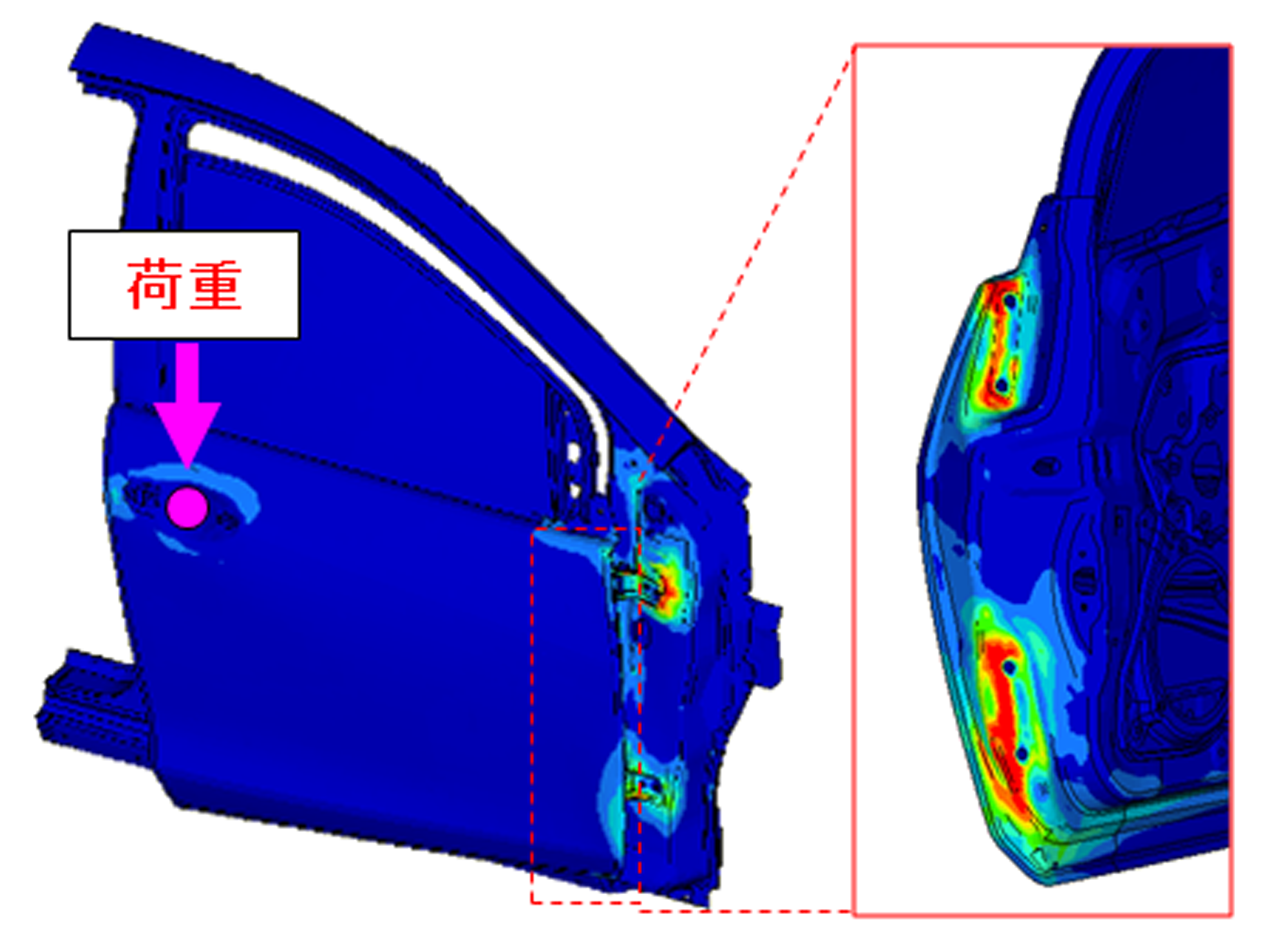
Worked on reinforcement layouts and tubular elements, where crash simulations provided CAE-driven design modifications for intrusion resistance and energy absorption.
Optimized carryover vs new parts to achieve cost reduction while meeting strength, weight, and safety targets.
Subsystem Design & Packaging
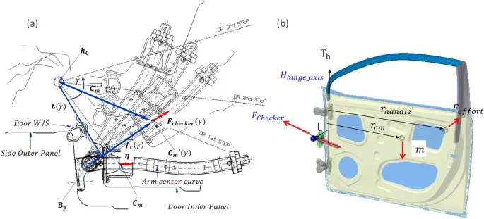
Latch and Mechanisms: Developed layouts for hinges, door checkers, and latch systems while ensuring compliance with ECE R11 latch/retention regulations. Mechanism kinematics were optimized for durability and ergonomic feel.
Glass & Regulator System: Designed the sash and reinforcement structures for smooth glass movement, with proper guidance, anti-rattle measures, and sealing considerations.
Sealing Surfaces: Engineered periphery sealing and glass run channels to achieve required NVH performance and water-tightness, balancing sealing efficiency with low effort door closing.
Electrical Integration: Coordinated layouts for wiring harness routing, connectors, switches, and sensors within the door, ensuring ease of assembly and serviceability.

Collaboration & Cross-Functional Work
Actively collaborated with press shop, weld shop, and paint shop teams to validate manufacturability and incorporate shop-floor feedback into early design stages.
Benchmarked competitor door systems and prepared internal databases of design solutions, enabling quicker design decisions and innovation.
Reviewed Tier-1 and Tier-2 supplier parts for feasibility, fitment, and compliance, while supporting senior engineers with documentation and technical evaluations.
Validation & Release
Released CAD models and drawings under strict deadlines, aligning with Suzuki’s design methodology and internal quality standards.
Supported vehicle-level door testing at the company’s proving grounds, gaining exposure to DVP activities such as durability cycling, water leakage checks, and abuse testing.
Conducted weekly door system review meetings, driving issue resolution, sharing knowledge across the department, and presenting learnings from supplier visits and industry expos.
Driving the EV Revolution: Designing and Programming Automated Production Machinery from Scratch.
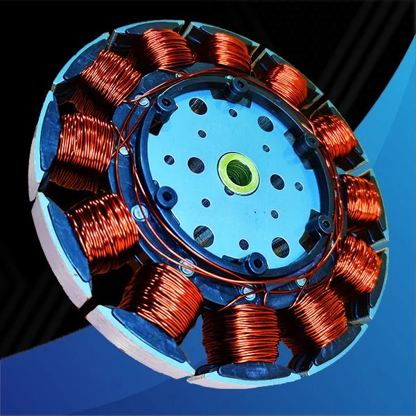
1. Winding Machine for E-Motors

I began with the design of a 2-station automatic stator winding machine for BLDC smart fans, which went into production. The system could wind two stators in 24 minutes and required a complete electromechanical design cycle.
Mechanically, I selected motors, gearboxes, and a synchronous belt drive system, and produced GD&T-compliant drawings for both fan parts and machine components. To deepen my understanding of tolerances and fits, I also manufactured many parts myself on manual milling and lathe machines.
On the electrical and controls side, I carried out the full wiring and wrote the
G-Code program to run the machine. This project was where connected mechanical design, manufacturing, and system integration, learning how theoretical calculations translate into production throughput.

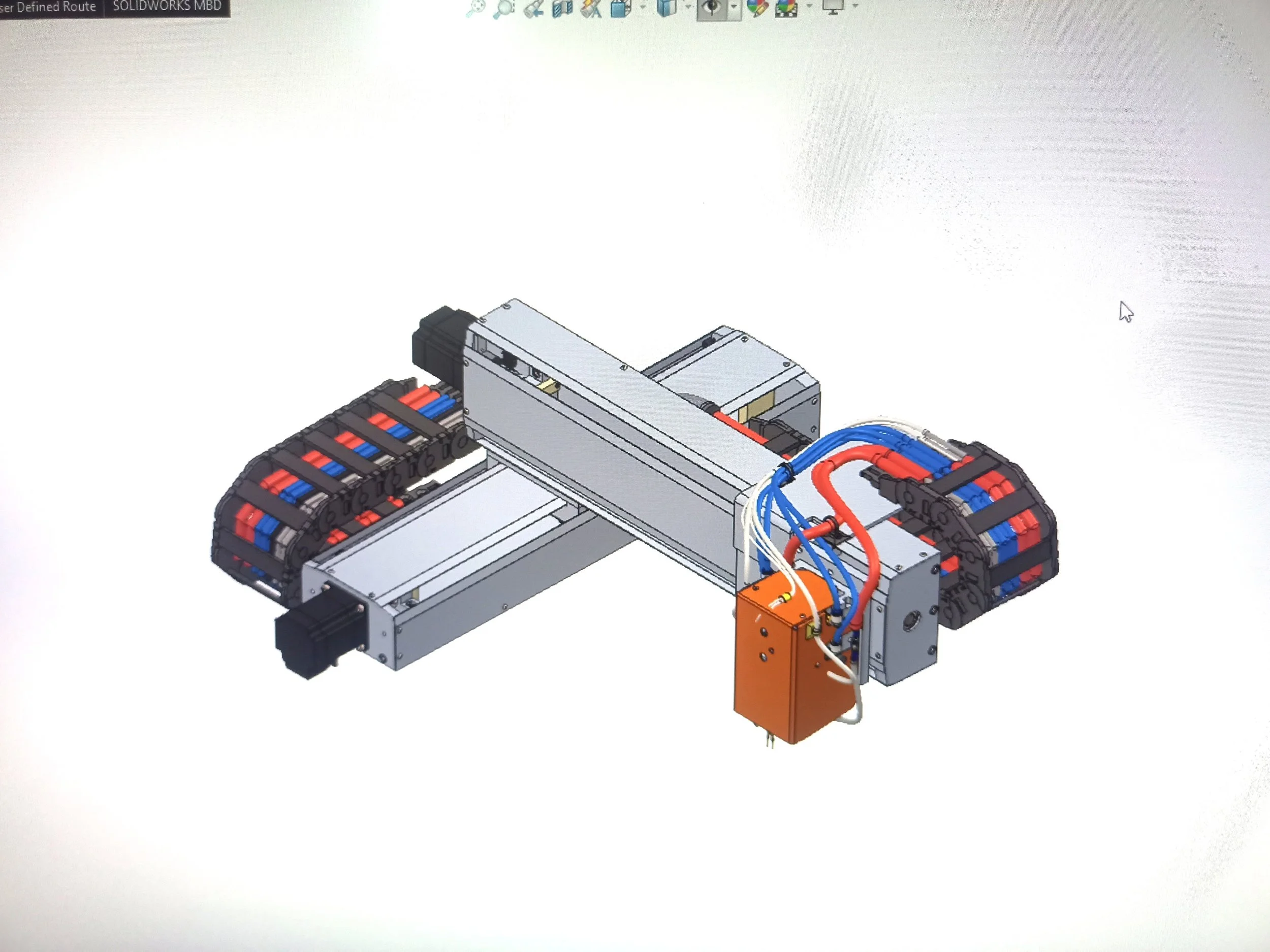
2. Automatic Spot Welding Machine

Building on the experience from the winding machine, I undertook a much larger and more complex project: designing a CNC-controlled spot-welding unit with pneumatic head actuation for EV battery pack assembly.
I created a CAD assembly of ~1300 components, covering welded frames, CNC-machined parts, and sheet-metal enclosures. Detailed speed, load, and accuracy calculations guided the selection of ball screws and linear guides.
I also handled the complete electrical and controls integration. This included drafting the full schematic and designing the control panel with CNC controller, limit/home switches, E-Stop, solenoid valves for pneumatics, hall sensors, load cells, and pressure sensors.
A critical aspect was the routing of shielded signal cables, power cables, and pneumatic hoses using energy chains, while applying proper grounding techniques to minimize EMI.
Compared to the winding machine, this project required a deeper grasp of design for manufacturability, metrology, and cross-discipline system integration, effectively bridging CAD, machining, electronics, and automation.


SCARA Robot for a robotic kitchen

Version 1:
The base used a NEMA 17 stepper with 2:1 pulley and 280 mm belt, but rotation on a PTFE washer was rough, the motor was exposed, mounting points looked bulky, and a custom bolt fit too tight. Linear motion used an 8 mm, 2 mm pitch lead screw with NEMA 17 and initially only 2 rods, which caused binding; later 3 rods with staggered bearings fixed alignment.
Still, the motor had no cover and the elbow motor sat in front of the screw, creating cantilever load and reducing capacity. The elbow (axis 3) ran on a NEMA 17 with 2:1 pulley but suffered joint bending from clearance between bolt and bearings, lacked a limit switch, and had no wiring provision. The gripper used 2 MG996 servos for wrist and jaws, but assembly was time-consuming and mechanically complex.
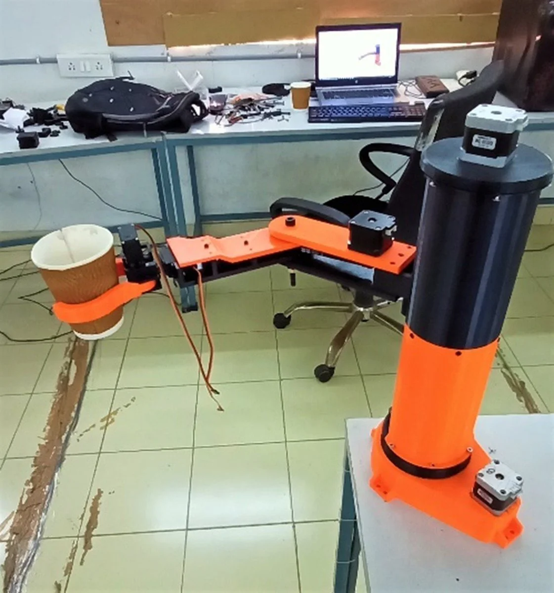
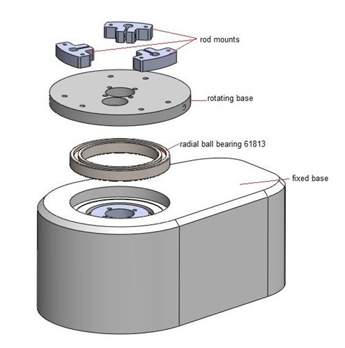
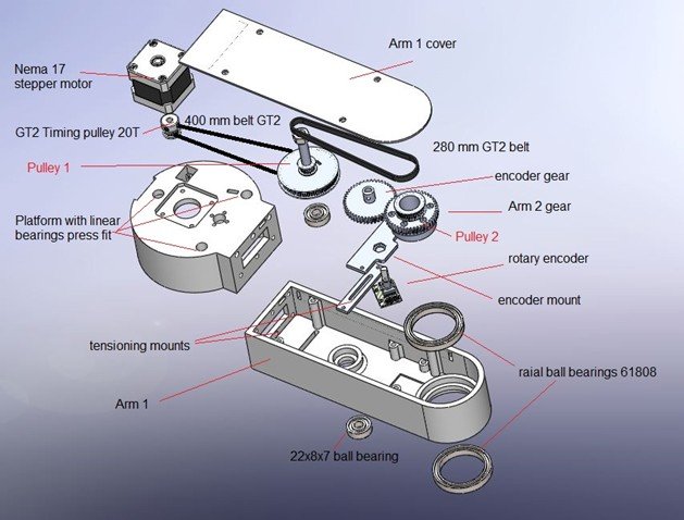
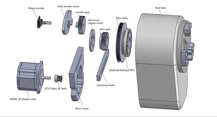
Version 2:
The base was improved with radial ball bearings for smooth rotation, a rotary encoder and hall sensor for tracking and homing, higher pulley ratio for torque, and an enclosed motor inside the base. Linear motion had a redesigned platform with wiring integration, provision for a cable drag chain, and a covered top motor. The elbow was completely redesigned to include encoder, hall sensor, belt-tensioning mounts, a protective cover, and proper wiring paths. The gripper remained unchanged from Version 1 since performance was adequate.